23 KiB
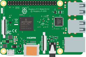
Raspberry Pi 3 Emulation (BCM2837 / ARM Cortex-A53)
Status: Functional · Backend QEMU process · WebSocket communication Engine: QEMU 8.1.3 (
qemu-system-aarch64 -M raspi3b) Platform: BCM2837 ARM Cortex-A53 @ 1.2 GHz — 64-bit ARMv8, quad-core Runs: Python scripts (Raspberry Pi OS Trixie) — no Arduino compilation needed Available on: all platforms (Windows, macOS, Linux, Docker)
Table of Contents
- Overview
- Supported Boards
- Emulator Architecture
- System Components
- Boot Sequence — Step by Step
- GPIO Shim — How Python Controls GPIO
- WebSocket Protocol
- Serial Communication (UART)
- Pin Mapping — Physical to BCM GPIO
- Virtual File System (VFS)
- Multi-Board Integration — Pi + Arduino
- Boot Images
- QEMU Launch Command
- Known Limitations
- Differences vs Other Emulators
- Key Files
1. Overview
The Raspberry Pi 3B is a full Linux single-board computer based on the Broadcom BCM2837 SoC (4× ARM Cortex-A53, ARMv8 64-bit). Unlike the other boards in Velxio — which compile and run Arduino C++ code — the Raspberry Pi 3 emulation boots a real Raspberry Pi OS (Trixie) inside QEMU and lets you run Python scripts that interact with GPIO.
There is no compilation step for the Raspberry Pi: you write a Python script in the editor, the backend uploads it to the emulated filesystem, and the Pi OS executes it directly.
Emulation Engine Comparison
| Board | Engine | Location | Language |
|---|---|---|---|
| Arduino Uno / Nano / Mega | avr8js | Browser | C++ (Arduino) |
| Raspberry Pi Pico | rp2040js | Browser | C++ (Arduino) |
| ESP32-C3 / XIAO-C3 | RiscVCore.ts | Browser | C++ (Arduino) |
| ESP32 / ESP32-S3 | QEMU lcgamboa (Xtensa) | Backend WebSocket | C++ (Arduino) |
| Raspberry Pi 3B | QEMU 8.1.3 (raspi3b) | Backend WebSocket | Python |
Key Differences from Arduino-based Boards
- No FQBN — no arduino-cli compilation; the board kind has
FQBN = null - Boots a real OS — Raspberry Pi OS Trixie runs inside QEMU (~2–5 seconds boot time)
- Python runtime — scripts use
RPi.GPIO(or a compatible shim) to interact with GPIO - Persistent storage — the OS image is a real disk image; a qcow2 overlay is used per session so the base image is never modified
- Multi-board serial — the Pi can communicate with co-simulated Arduino boards via virtual serial lines
2. Supported Boards
 Raspberry Pi 3B |
| Board | QEMU Machine | CPU | Notes |
|---|---|---|---|
| Raspberry Pi 3B | raspi3b |
BCM2837, 4× Cortex-A53 | Full Raspberry Pi OS support |
Raspberry Pi 3B+ and Pi 4 are not currently supported. The
raspi3bmachine type in QEMU closely matches the standard 3B hardware.
3. Emulator Architecture
Python Script (user writes in editor)
        │
        ▼  (uploaded via WebSocket / VFS)
  /home/pi/script.py  (inside Raspberry Pi OS)
        │
        ▼  python3 /home/pi/script.py
  RPi.GPIO (shim)  ←  intercepted by gpio_shim.py
        │
        ├── GPIO.output(17, HIGH)  →  "GPIO 17 1\n"  →  ttyAMA1  →  Backend
        │                                                             │
        │                                                             ▼
        │                                                      gpio_change event
        │                                                      WebSocket → Frontend
        │                                                      PinManager → LED visual
        │
        └── Serial.print()  →  ttyAMA0  →  Backend  →  serial_output  →  Serial Monitor
Communication Channels
The Raspberry Pi uses two independent TCP serial ports exposed through QEMU:
| Channel | QEMU Serial | TCP Port | Purpose |
|---|---|---|---|
| User Serial | -serial tcp:...:N |
dynamic | User print() output and input() — visible in Serial Monitor |
| GPIO Protocol | -serial tcp:...:M |
dynamic | GPIO shim protocol (GPIO <pin> <val>\n) |
Both ports are allocated dynamically at startup to avoid conflicts on the host machine.
4. System Components
Backend
| Component | File | Responsibility |
|---|---|---|
QemuManager |
backend/app/services/qemu_manager.py |
Singleton that manages all Pi instances (one per WebSocket client) |
PiInstance |
backend/app/services/qemu_manager.py |
Runtime state for one running Pi: QEMU process, TCP ports, overlay path |
gpio_shim |
backend/app/services/gpio_shim.py |
RPi.GPIO drop-in replacement; speaks the GPIO text protocol over ttyAMA1 |
| WebSocket route | backend/app/api/routes/simulation.py |
GET /api/simulation/ws/{client_id} — bidirectional JSON message bus |
Frontend
| Component | File | Responsibility |
|---|---|---|
RaspberryPi3Bridge |
frontend/src/simulation/RaspberryPi3Bridge.ts |
WebSocket connection manager; sends/receives JSON messages |
useSimulatorStore |
frontend/src/store/useSimulatorStore.ts |
Zustand store; wires bridge events to board state and pin manager |
useVfsStore |
frontend/src/store/useVfsStore.ts |
Virtual filesystem tree per board; Python script editing |
RaspberryPi3.tsx |
frontend/src/components/components-wokwi/RaspberryPi3.tsx |
React board component (SVG image, 40-pin header) |
boardPinMapping.ts |
frontend/src/utils/boardPinMapping.ts |
Physical pin → BCM GPIO number translation |
5. Boot Sequence — Step by Step
1. User clicks "Start" (or "Run")
        │
        ▼
2. SimulatorCanvas detects board kind 'raspberry-pi-3'
   → calls startBoard(boardId)

3. useSimulatorStore calls RaspberryPi3Bridge.connect()

4. Bridge opens WebSocket:
   ws://localhost:8001/api/simulation/ws/<boardId>
   → sends { type: 'start_pi', data: { board: 'raspberry-pi-3' } }

5. Backend (simulation.py) routes to:
   QemuManager.start_instance(client_id, 'raspberry-pi-3', callback)

6. QemuManager._boot(inst):
   a. Allocate two free TCP ports (serial_port, gpio_port)
   b. Create qcow2 overlay over base SD image:
      qemu-img create -f qcow2 -b raspios.img overlay_<id>.qcow2
   c. Launch qemu-system-aarch64 (see Section 13 for full command)
   d. Emit { type: 'system', event: 'booting' }

7. Wait ~2 seconds for QEMU to initialize TCP servers

8. QemuManager._connect_serial(inst):
   → Connect to ttyAMA0 TCP socket
   → Start async reader loop (forwards bytes as serial_output events)
   → Emit { type: 'system', event: 'booted' }

9. QemuManager._connect_gpio(inst):
   → Connect to ttyAMA1 TCP socket
   → Start async reader loop (parses "GPIO <pin> <val>\n" lines)

10. Frontend receives 'booted' event
    → Board UI updates to "running" state
    → Serial Monitor shows first Linux kernel output

11. Python script runs:
    → python3 /home/pi/script.py (auto-launched via -append init=/bin/sh)
6. GPIO Shim — How Python Controls GPIO
The gpio_shim.py module is injected into the Raspberry Pi OS at the standard RPi.GPIO installation path:
/usr/local/lib/python3.11/dist-packages/RPi/GPIO.py
When a Python script does import RPi.GPIO as GPIO, it gets this shim instead of the real hardware driver. The shim communicates over /dev/ttyAMA1 (the second QEMU serial port) using a simple text protocol.
GPIO Text Protocol
Pi → Backend  (output state change):
    "GPIO <bcm_pin> <0|1>\n"
    Example: "GPIO 17 1\n"  ← GPIO 17 driven HIGH

Backend → Pi  (external input, e.g. button press from canvas):
    "SET <bcm_pin> <0|1>\n"
    Example: "SET 22 1\n"  ← button wired to GPIO 22 pressed
Supported RPi.GPIO API
import RPi.GPIO as GPIO

# Numbering mode
GPIO.setmode(GPIO.BCM)    # use BCM numbers (GPIO17, GPIO22, ...)
GPIO.setmode(GPIO.BOARD)  # use physical pin numbers (11, 15, ...)

# Pin direction
GPIO.setup(17, GPIO.OUT)
GPIO.setup(22, GPIO.IN, pull_up_down=GPIO.PUD_UP)

# Digital output
GPIO.output(17, GPIO.HIGH)   # → sends "GPIO 17 1\n" to backend
GPIO.output(17, GPIO.LOW)    # → sends "GPIO 17 0\n" to backend
GPIO.output(17, True)        # equivalent to GPIO.HIGH

# Digital input
state = GPIO.input(22)       # reads last known state (updated by "SET" messages)

# Event detection
GPIO.add_event_detect(22, GPIO.RISING, callback=my_callback)
GPIO.add_event_detect(22, GPIO.FALLING, callback=my_callback)
GPIO.add_event_detect(22, GPIO.BOTH, callback=my_callback)

# PWM (simplified — simulated as digital output)
pwm = GPIO.PWM(18, 1000)   # pin 18, 1000 Hz
pwm.start(75)              # 75% duty cycle → HIGH (duty > 50% → HIGH, else LOW)
pwm.ChangeDutyCycle(25)    # 25% duty cycle → LOW
pwm.stop()

# Cleanup
GPIO.cleanup()
GPIO.cleanup(17)           # clean specific pin
PWM limitation: The shim does not implement real PWM waveforms. It converts duty cycle to a binary state:
duty > 50→ HIGH,duty ≤ 50→ LOW. Visual LED dimming is not supported for Pi GPIO PWM.
Example Python Script (Blink LED)
#!/usr/bin/env python3
import time
import RPi.GPIO as GPIO

GPIO.setmode(GPIO.BCM)
GPIO.setup(17, GPIO.OUT)

try:
    while True:
        GPIO.output(17, GPIO.HIGH)
        print("LED ON")
        time.sleep(1)
        GPIO.output(17, GPIO.LOW)
        print("LED OFF")
        time.sleep(1)
finally:
    GPIO.cleanup()
7. WebSocket Protocol
All communication between the frontend and backend passes through a single WebSocket connection per board instance.
Endpoint: GET /api/simulation/ws/{client_id}
Frontend → Backend Messages
| Message Type | Payload | Description |
|---|---|---|
start_pi |
{ board: "raspberry-pi-3" } |
Launch QEMU, start the Pi |
stop_pi |
(empty) | Stop QEMU, clean up overlay |
serial_input |
{ bytes: number[] } |
Send bytes to ttyAMA0 (Serial Monitor → Pi) |
gpio_in |
{ pin: number, state: 0|1 } |
Inject external GPIO state (button press from canvas) |
Backend → Frontend Messages
| Message Type | Payload | Description |
|---|---|---|
serial_output |
{ data: string } |
String data from ttyAMA0 (Pi print output) |
gpio_change |
{ pin: number, state: 0|1 } |
A GPIO pin changed state (driven by Python script) |
system |
{ event: "booting"|"booted"|"exited" } |
Boot lifecycle events |
error |
{ message: string } |
Error from QEMU or backend |
8. Serial Communication (UART)
The Raspberry Pi 3 exposes two UART ports through QEMU:
| Port | Device | Physical Pins | Role |
|---|---|---|---|
| UART0 (ttyAMA0) | /dev/ttyAMA0 |
GPIO14 (TX), GPIO15 (RX) | User serial — print() output, input(), serial.Serial() |
| UART1 (ttyAMA1) | /dev/ttyAMA1 |
— (internal) | GPIO shim protocol — reserved, not accessible to user scripts |
Serial Monitor Integration
Anything the Python script writes to stdout or to /dev/ttyAMA0 appears in the Serial Monitor panel:
# stdout (print) — captured automatically
print("Hello from Pi!")

# Direct ttyAMA0 (explicit serial)
import serial
port = serial.Serial('/dev/ttyAMA0', baudrate=9600, timeout=1)
port.write(b"Hello Arduino!\n")
Sending Text to the Pi
Text typed in the Serial Monitor input box is sent to ttyAMA0 as a serial_input message, which the Pi receives via input() or by reading /dev/ttyAMA0.
9. Pin Mapping — Physical to BCM GPIO
The Raspberry Pi 3B has a standard 40-pin GPIO header (2 rows × 20 columns). The table below shows the mapping from physical pin number to BCM GPIO number:
| Physical | BCM | Function | Physical | BCM | Function |
|---|---|---|---|---|---|
| 1 | — | 3.3 V | 2 | — | 5 V |
| 3 | 2 | I2C1 SDA | 4 | — | 5 V |
| 5 | 3 | I2C1 SCL | 6 | — | GND |
| 7 | 4 | GPIO | 8 | 14 | UART TX |
| 9 | — | GND | 10 | 15 | UART RX |
| 11 | 17 | GPIO | 12 | 18 | PWM0 |
| 13 | 27 | GPIO | 14 | — | GND |
| 15 | 22 | GPIO | 16 | 23 | GPIO |
| 17 | — | 3.3 V | 18 | 24 | GPIO |
| 19 | 10 | SPI MOSI | 20 | — | GND |
| 21 | 9 | SPI MISO | 22 | 25 | GPIO |
| 23 | 11 | SPI SCLK | 24 | 8 | SPI CE0 |
| 25 | — | GND | 26 | 7 | SPI CE1 |
| 27 | — | ID_SD | 28 | — | ID_SC |
| 29 | 5 | GPIO | 30 | — | GND |
| 31 | 6 | GPIO | 32 | 12 | PWM0 |
| 33 | 13 | PWM1 | 34 | — | GND |
| 35 | 19 | SPI1 MISO | 36 | 16 | SPI1 CE2 |
| 37 | 26 | GPIO | 38 | 20 | SPI1 MOSI |
| 39 | — | GND | 40 | 21 | SPI1 SCLK |
Pins 27 and 28 are reserved for ID EEPROM. Power and GND pins have BCM = —.
Pin Resolution in Frontend
// Wire connects physical pin "8" on the Pi board
boardPinToNumber('raspberry-pi-3', '8')      // → 14 (BCM GPIO14, UART TX)
boardPinToNumber('raspberry-pi-3', 'GPIO17') // → 17
boardPinToNumber('raspberry-pi-3', 'GND')    // → null (not a GPIO)
10. Virtual File System (VFS)
Each Raspberry Pi 3 board instance has its own virtual filesystem tree stored in the useVfsStore Zustand store. This lets you create and edit Python scripts directly in the Velxio editor before they are uploaded to the Pi.
Default VFS Tree
/
└── home/
    └── pi/
        ├── script.py     ← main Python script (editable)
        └── hello.sh      ← example shell script
Default script.py
#!/usr/bin/env python3
import time
import RPi.GPIO as GPIO

GPIO.setmode(GPIO.BCM)
GPIO.setup(17, GPIO.OUT)

while True:
    GPIO.output(17, GPIO.HIGH)
    print("LED on")
    time.sleep(1)
    GPIO.output(17, GPIO.LOW)
    print("LED off")
    time.sleep(1)
VFS API
const vfs = useVfsStore.getState();

vfs.initBoardVfs(boardId)                          // create default tree
vfs.createNode(boardId, parentId, 'app.py', 'file') // add new file
vfs.setContent(boardId, nodeId, pythonCode)         // update file content
vfs.serializeForUpload(boardId)                     // returns [{ path, content }, ...]
Files in the VFS are uploaded to the Pi OS at boot via the WebSocket connection before the script is executed.
11. Multi-Board Integration — Pi + Arduino
The Raspberry Pi 3 can be placed on the same canvas as Arduino or other boards. When wires connect a Pi GPIO pin to an Arduino pin, the stores route data between them automatically.
Pi → Arduino (Serial TX)
Pi Python script:
    port.write(b"LED_ON\n")
        │
        ▼  ttyAMA0 byte output
  serial_output WebSocket message
        │
        ▼  useSimulatorStore (serial callback)
  AVRSimulator.serialWrite("L")  ←  feeds byte into Arduino RX FIFO
        │
        ▼  Arduino sketch:
  String cmd = Serial.readStringUntil('\n');
  if (cmd == "LED_ON") digitalWrite(8, HIGH);
Arduino → Pi (Serial RX)
Arduino sketch:
    Serial.println("SENSOR:1023");
        │
        ▼  USART byte emitted
  useSimulatorStore serial callback
        │
        ▼  bridge.sendSerialBytes([charCode, ...])
  serial_input WebSocket message → Backend
        │
        ▼  qemu_manager.send_serial_bytes(client_id, bytes)
  ttyAMA0 receives bytes → Pi reads with:
  line = port.readline()  # "SENSOR:1023\n"
Example Project: Pi + Arduino LED Control
This example (included in the gallery as pi-to-arduino-led-control) demonstrates bidirectional serial communication:
Pi Script:
import serial, time

port = serial.Serial('/dev/ttyAMA0', baudrate=9600, timeout=1)

for _ in range(3):
    port.write(b"LED1_ON\n")
    time.sleep(0.5)
    port.write(b"LED1_OFF\n")
    time.sleep(0.5)

port.write(b"LED2_ON\n")
time.sleep(2)
port.write(b"LED2_OFF\n")
Arduino Sketch:
const int LED1 = 8, LED2 = 9;

void setup() {
  Serial.begin(9600);
  pinMode(LED1, OUTPUT);
  pinMode(LED2, OUTPUT);
}

void loop() {
  if (Serial.available()) {
    String cmd = Serial.readStringUntil('\n');
    if      (cmd == "LED1_ON")  digitalWrite(LED1, HIGH);
    else if (cmd == "LED1_OFF") digitalWrite(LED1, LOW);
    else if (cmd == "LED2_ON")  digitalWrite(LED2, HIGH);
    else if (cmd == "LED2_OFF") digitalWrite(LED2, LOW);
  }
}
12. Boot Images
QEMU needs three files from the /img/ directory to boot the Raspberry Pi 3:
| File | Size | Description |
|---|---|---|
kernel8.img |
~6 MB | ARM64 Linux kernel extracted from Raspberry Pi OS Trixie |
bcm271~1.dtb |
~40 KB | Device tree binary — defines CPU, RAM, peripheral base addresses |
2025-12-04-raspios-trixie-armhf.img |
~5.67 GB | Full Raspberry Pi OS SD card image (root filesystem) |
The base SD image is never modified. Each session creates a qcow2 copy-on-write overlay (
overlay_<session_id>.qcow2) that records only the changes made during that session. The overlay is automatically deleted when the session ends.
Creating the Overlay at Runtime
# Backend does this automatically for each session:
qemu-img create -f qcow2 \
  -b /img/2025-12-04-raspios-trixie-armhf.img \
  /tmp/overlay_<session_id>.qcow2
13. QEMU Launch Command
qemu-system-aarch64 \
  -M raspi3b \
  -kernel /img/kernel8.img \
  -dtb    /img/bcm271~1.dtb \
  -drive  file=/tmp/overlay_<id>.qcow2,if=sd,format=qcow2 \
  -m 1G \
  -smp 4 \
  -nographic \
  -serial tcp:127.0.0.1:<serial_port>,server,nowait \
  -serial tcp:127.0.0.1:<gpio_port>,server,nowait \
  -append 'console=ttyAMA0 root=/dev/mmcblk0p2 rootwait rw \
           dwc_otg.lpm_enable=0 quiet init=/bin/sh'
Key Flags
| Flag | Value | Meaning |
|---|---|---|
-M raspi3b |
machine type | Emulate the Raspberry Pi 3B hardware |
-m 1G |
RAM | 1 GB RAM (matches real Pi 3B) |
-smp 4 |
CPU cores | 4 ARM Cortex-A53 cores |
-nographic |
no display | No HDMI/video output — serial only |
-serial tcp:...:N,server,nowait |
first serial | ttyAMA0 (user serial) served on TCP port N |
-serial tcp:...:M,server,nowait |
second serial | ttyAMA1 (GPIO shim protocol) served on TCP port M |
-append ... init=/bin/sh |
kernel cmdline | Boot straight to a shell (skips systemd login) |
-drive ...,format=qcow2 |
disk | qcow2 overlay over the base SD image |
14. Known Limitations
| Limitation | Detail |
|---|---|
| Boot time | QEMU takes 2–5 seconds to start; the frontend shows a "booting" state during this time |
| No real PWM | GPIO.PWM simulates duty cycle as binary state (>50% = HIGH, ≤50% = LOW); no analog dimming |
| No I2C emulation | smbus, smbus2, i2c_msg — I2C bus transactions are not forwarded to virtual devices |
| No SPI emulation | Hardware SPI registers not forwarded; spidev library will fail |
| Single UART for GPIO | ttyAMA1 is reserved for the GPIO shim; scripts cannot use it for other serial devices |
| No GUI / display | HDMI output is disabled (-nographic); GUI Python libraries (Tkinter, pygame, etc.) will not work |
| No networking | QEMU does not expose a network interface; requests, socket, urllib will fail |
| No persistent state | The qcow2 overlay is deleted after shutdown; files written to the Pi OS do not survive a restart |
| Reset is reconnect | resetBoard() is not implemented; to restart the Pi, stop it and start it again |
| Session isolation | Each board instance creates an independent QEMU process; two Pi boards do not share any state |
| Resource usage | Each Pi instance launches a full QEMU process (~200 MB RAM); hosting many simultaneous sessions is resource-intensive |
15. Differences vs Other Emulators
| Aspect | Raspberry Pi 3B | Raspberry Pi Pico | ESP32 (Xtensa) | Arduino AVR |
|---|---|---|---|---|
| Engine | QEMU raspi3b | rp2040js (browser) | QEMU lcgamboa (backend) | avr8js (browser) |
| Backend required | Yes (QEMU process) | No | Yes (QEMU process) | No |
| Language | Python | C++ (Arduino) | C++ (Arduino) | C++ (Arduino) |
| Compilation step | No | Yes (arduino-cli) | Yes (arduino-cli) | Yes (arduino-cli) |
| OS | Raspberry Pi OS (Linux) | None (bare metal) | None (ESP-IDF) | None (bare metal) |
| Boot time | ~2–5 s | Instant | ~1–2 s | Instant |
| GPIO protocol | Text over ttyAMA1 | MMIO direct | QEMU callbacks + WebSocket | Port listeners |
| Serial | ttyAMA0 (real UART) | UART0/1 (rp2040js) | UART0 (QEMU) | USART0 (avr8js) |
| I2C | Not forwarded to frontend | 2 buses + virtual devices | Emulated | Not emulated |
| PWM | Binary (no waveform) | Hardware PWM | LEDC (mapped) | Timer-based |
| Multi-board comms | Yes (serial bridge) | No | No | No |
| Oscilloscope | No | Yes (8 ns resolution) | No | Yes |
| CI tests | No | Yes (Vitest) | No | Yes (Vitest) |
| Disk image required | Yes (~5.67 GB) | No | No | No |
16. Key Files
| File | Description |
|---|---|
backend/app/services/qemu_manager.py |
QemuManager — manages QEMU process lifecycle, TCP sockets, qcow2 overlays |
backend/app/services/gpio_shim.py |
RPi.GPIO drop-in replacement; speaks text protocol over ttyAMA1 |
backend/app/api/routes/simulation.py |
WebSocket endpoint /api/simulation/ws/{client_id} |
frontend/src/simulation/RaspberryPi3Bridge.ts |
WebSocket client; routes serial_output, gpio_change, system events |
frontend/src/store/useSimulatorStore.ts |
Board lifecycle, serial bridge to co-simulated AVR/Pico boards |
frontend/src/store/useVfsStore.ts |
Per-board virtual filesystem (Python script editor) |
frontend/src/utils/boardPinMapping.ts |
Physical pin → BCM GPIO number mapping table |
frontend/src/components/components-wokwi/RaspberryPi3.tsx |
Board React component (SVG, 40-pin header coordinates) |
frontend/src/components/components-wokwi/RaspberryPi3Element.ts |
Web Component for canvas rendering and wire endpoints |
frontend/src/types/board.ts |
BoardKind type, FQBN = null for Raspberry Pi 3 |
img/kernel8.img |
ARM64 kernel extracted from Raspberry Pi OS Trixie |
img/bcm271~1.dtb |
Device tree binary for BCM2837 |
img/2025-12-04-raspios-trixie-armhf.img |
Raspberry Pi OS SD image (~5.67 GB) — base for qcow2 overlays |