48 KiB
ESP32 Emulation (Xtensa) — Technical Documentation
Status: Functional · Backend complete · Frontend complete Engine: lcgamboa/qemu-8.1.3 · Platform: arduino-esp32 2.0.17 (IDF 4.4.x) Available on: Windows (
.dll) · Linux / Docker (.so, included in the official image) Applies to: ESP32, ESP32-S3 (Xtensa LX6/LX7 architecture)
Note on ESP32-C3: The ESP32-C3, XIAO ESP32-C3, and ESP32-C3 SuperMini boards use the RISC-V RV32IMC architecture and are emulated via
libqemu-riscv32(same backend pattern as Xtensa, different library and machine). See → RISCV_EMULATION.md
Supported Boards
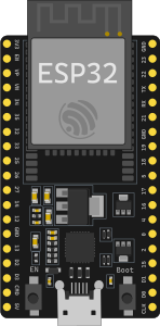 ESP32 DevKit C V4 |
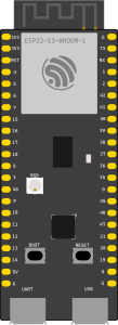 ESP32-S3 |
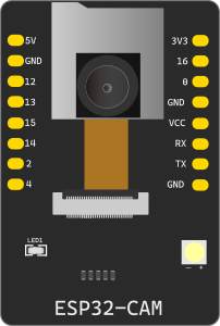 ESP32-CAM |
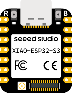 Seeed XIAO ESP32-S3 |
 Arduino Nano ESP32 |
Table of Contents
- Quick Setup — Windows
- Quick Setup — Docker / Linux
- General Architecture
- System Components
- Firmware — Requirements for lcgamboa
- Emulated WiFi
- Emulated I2C
- RMT / NeoPixel (WS2812)
- LEDC / PWM and GPIO Mapping
- Building the Library Manually
- Tests
- Frontend — Implemented Events
- Known Limitations
- Environment Variables
- GPIO Banks — GPIO32-39 Fix
- UI Interaction — ADC, Buttons, and Visual PWM
- lcgamboa Fork Modifications — Incremental Rebuild
1. Quick Setup — Windows
This section covers everything needed to get ESP32 emulation running from scratch on Windows.
1.1 System Prerequisites
| Tool | Minimum Version | Purpose |
|---|---|---|
| Python | 3.11+ | FastAPI backend |
| MSYS2 | any | Build the QEMU DLL |
| arduino-cli | 1.x | Compile ESP32 sketches |
| esptool | 4.x or 5.x | Create 4 MB flash images |
| Git | 2.x | Clone the qemu-lcgamboa submodule |
1.2 Install MSYS2
Download and install from msys2.org or via winget:
winget install MSYS2.MSYS2
Open the MSYS2 MINGW64 terminal and run:
pacman -Syu   # update base

pacman -S \
  mingw-w64-x86_64-gcc \
  mingw-w64-x86_64-glib2 \
  mingw-w64-x86_64-libgcrypt \
  mingw-w64-x86_64-libslirp \
  mingw-w64-x86_64-pixman \
  mingw-w64-x86_64-ninja \
  mingw-w64-x86_64-meson \
  mingw-w64-x86_64-python \
  mingw-w64-x86_64-pkg-config \
  git diffutils
1.3 Install arduino-cli and the ESP32 2.0.17 Core
# Install arduino-cli (if not already installed)
winget install ArduinoSA.arduino-cli

# Verify
arduino-cli version

# Add ESP32 support
arduino-cli core update-index
arduino-cli core install esp32:esp32@2.0.17   # ← IMPORTANT: 2.x, NOT 3.x

# Verify
arduino-cli core list   # should show esp32:esp32  2.0.17
Why 2.0.17 and not 3.x? The lcgamboa emulated WiFi periodically disables the SPI flash cache. In IDF 5.x (arduino-esp32 3.x) this causes a cache crash when core 0 interrupts try to execute code from IROM. IDF 4.4.x has different, compatible cache behavior.
1.4 Install esptool
pip install esptool
# Verify
esptool version   # or: python -m esptool version
1.5 Build the QEMU DLL (libqemu-xtensa.dll)
The DLL is the main emulation engine. It needs to be compiled once from the wokwi-libs/qemu-lcgamboa submodule.
# Make sure you have the submodule
git submodule update --init wokwi-libs/qemu-lcgamboa

# In the MSYS2 MINGW64 terminal:
cd /e/Hardware/wokwi_clon/wokwi-libs/qemu-lcgamboa
bash build_libqemu-esp32-win.sh
# Produces: build/libqemu-xtensa.dll and build/libqemu-riscv32.dll
Copy the DLL to the backend:
cp build/libqemu-xtensa.dll /e/Hardware/wokwi_clon/backend/app/services/
Verify the DLL was created:
ls -lh backend/app/services/libqemu-xtensa.dll
# → should be ~40-50 MB
Verify exports:
objdump -p backend/app/services/libqemu-xtensa.dll | grep -i "qemu_picsimlab\|qemu_init"
# → should show qemu_init, qemu_main_loop, qemu_picsimlab_register_callbacks, etc.
1.6 Obtain the ESP32 ROM Binaries
The DLL requires two ROM files from Espressif to boot the ESP32. They must be placed in the same folder as the DLL:
Option A — From esp-qemu (if installed):
copy "C:\esp-qemu\qemu\share\qemu\esp32-v3-rom.bin" backend\app\services\
copy "C:\esp-qemu\qemu\share\qemu\esp32-v3-rom-app.bin" backend\app\services\
Option B — From the lcgamboa submodule (easier):
cp wokwi-libs/qemu-lcgamboa/pc-bios/esp32-v3-rom.bin backend/app/services/
cp wokwi-libs/qemu-lcgamboa/pc-bios/esp32-v3-rom-app.bin backend/app/services/
Verify:
ls -lh backend/app/services/esp32-v3-rom.bin
ls -lh backend/app/services/esp32-v3-rom-app.bin
# → both ~446 KB
1.7 Install Backend Python Dependencies
cd backend
python -m venv venv
venv\Scripts\activate        # Windows
pip install -r requirements.txt
1.8 Verify Installation with Tests
# From the repo root (with venv activated):
python -m pytest test/esp32/test_esp32_lib_bridge.py -v

# Expected result: 28 passed in ~13 seconds
If you see 28 passed — the emulation is fully functional.
Additional tests (Arduino ↔ ESP32 serial):
python -m pytest test/esp32/test_arduino_esp32_integration.py -v
# Expected result: 13 passed
1.9 Start the Backend with ESP32 Emulation
cd backend
venv\Scripts\activate
uvicorn app.main:app --reload --port 8001
The system automatically detects the DLL. Verify in the logs:
INFO: libqemu-xtensa.dll found at backend/app/services/libqemu-xtensa.dll
INFO: EspLibManager: lib mode active (GPIO, ADC, UART, WiFi, I2C, SPI, RMT, LEDC)
If it does not appear, verify with:
python -c "
import sys; sys.path.insert(0,'backend')
from app.services.esp32_lib_manager import esp_lib_manager
print('lib available:', esp_lib_manager.is_available())
"
1.10 Compile Your Own ESP32 Sketch
# Compile with DIO flash mode (required by QEMU lcgamboa):
arduino-cli compile \
  --fqbn esp32:esp32:esp32:FlashMode=dio \
  --output-dir build/ \
  mi_sketch/

# Create a complete 4 MB image (required for QEMU):
esptool --chip esp32 merge_bin \
  --fill-flash-size 4MB \
  -o firmware.merged.bin \
  --flash_mode dio \
  --flash_size 4MB \
  0x1000  build/mi_sketch.ino.bootloader.bin \
  0x8000  build/mi_sketch.ino.partitions.bin \
  0x10000 build/mi_sketch.ino.bin
The firmware.merged.bin file is what gets loaded into the emulation.
2. Quick Setup — Docker / Linux
Full ESP32 emulation is included in the official Docker image. No additional installation is required — the libqemu-xtensa.so is compiled automatically during the image build from the lcgamboa fork.
2.1 Use the Pre-built Image (Recommended)
docker run -d \
  --name velxio \
  -p 3080:80 \
  -v $(pwd)/data:/app/data \
  -e SECRET_KEY=your-secret \
  ghcr.io/davidmonterocrespo24/velxio:master
ESP32 emulation with full GPIO is active automatically. No additional environment variables are needed.
2.2 Local Image Build
git clone https://github.com/davidmonterocrespo24/velxio.git
cd velxio
docker build -f Dockerfile.standalone -t velxio .
docker run -d -p 3080:80 -e SECRET_KEY=secret velxio
Build time note: QEMU compilation takes 15-30 minutes the first time. Subsequent builds use the Docker cached layer — they are instantaneous as long as the lcgamboa source has not changed.
2.3 Verify ESP32 Emulation in the Container
# Verify that .so and ROMs are present
docker exec <container_id> ls -lh /app/lib/

# Verify that ctypes can load the .so
docker exec <container_id> python3 -c \
  "import ctypes; ctypes.CDLL('/app/lib/libqemu-xtensa.so'); print('OK')"

# Verify that the manager detects it
docker exec <container_id> python3 -c \
  "import sys; sys.path.insert(0,'/app')
from app.services.esp32_lib_manager import esp_lib_manager
print('ESP32 lib available:', esp_lib_manager.is_available())"
2.4 Linux (without Docker)
If you run the backend directly on Linux:
# 1. Install runtime dependencies
sudo apt-get install -y libglib2.0-0 libgcrypt20 libslirp0 libpixman-1-0

# 2. Compile the .so (requires build tools)
sudo apt-get install -y git python3-pip ninja-build pkg-config flex bison \
    gcc g++ make libglib2.0-dev libgcrypt20-dev libslirp-dev libpixman-1-dev libfdt-dev
pip3 install meson

git clone --depth=1 --branch picsimlab-esp32 \
    https://github.com/lcgamboa/qemu /tmp/qemu-lcgamboa
cd /tmp/qemu-lcgamboa
bash build_libqemu-esp32.sh
# → build/libqemu-xtensa.so

# 3. Copy .so and ROMs next to the Python module
cp build/libqemu-xtensa.so /path/to/project/backend/app/services/
cp pc-bios/esp32-v3-rom.bin /path/to/project/backend/app/services/
cp pc-bios/esp32-v3-rom-app.bin /path/to/project/backend/app/services/

# 4. Start backend (auto-detects the .so)
cd /path/to/project/backend
uvicorn app.main:app --reload --port 8001
3. General Architecture
User (browser)
  └── WebSocket (/ws/{client_id})
        └── simulation.py  (FastAPI router)
              ├── EspLibManager          ← backend with .so/.dll (GPIO, WiFi, I2C, SPI, RMT…)
              └── EspQemuManager         ← UART-only fallback via subprocess
                    │
              [QEMU_ESP32_LIB=libqemu-xtensa.so|.dll]
                    │
              Esp32LibBridge (ctypes)
                    │
              libqemu-xtensa.so/.dll  ←  lcgamboa fork of QEMU 8.1.3
                    │
              Machine: esp32-picsimlab
                    │
         ┌──────────┴──────────┐
     CPU Xtensa LX6      emulated peripherals
     (dual-core)    GPIO · ADC · UART · I2C · SPI
                    RMT · LEDC · Timer · WiFi · Flash
The system selects the backend automatically:
- lib available →
EspLibManager(full GPIO + all peripherals) - lib absent →
EspQemuManager(UART serial only via TCP, QEMU subprocess)
Automatic detection:
| Platform | Library searched | Source |
|---|---|---|
| Docker / Linux | /app/lib/libqemu-xtensa.so |
Compiled in the Dockerfile |
| Windows (development) | backend/app/services/libqemu-xtensa.dll |
Compiled with MSYS2 |
| Custom | $QEMU_ESP32_LIB |
Environment variable |
4. System Components
4.1 libqemu-xtensa.so / libqemu-xtensa.dll
Compiled from the lcgamboa/qemu fork, branch picsimlab-esp32.
Runtime dependencies:
Windows (resolved automatically from C:\msys64\mingw64\bin\):
libglib-2.0-0.dll, libgcrypt-20.dll, libslirp-0.dll,
libgpg-error-0.dll, libintl-8.dll, libpcre2-8-0.dll  (+~15 MinGW64 DLLs)
Linux / Docker (system packages):
libglib2.0-0, libgcrypt20, libslirp0, libpixman-1-0
Required ROM binaries (in the same folder as the lib):
# Windows (backend/app/services/):
  libqemu-xtensa.dll        ← Xtensa engine for ESP32/S3 (not in git — 43 MB)
  libqemu-riscv32.dll       ← RISC-V engine for ESP32-C3 (not in git — 58 MB)
  esp32-v3-rom.bin          ← ESP32 boot ROM (not in git — 446 KB)
  esp32-v3-rom-app.bin      ← application ROM (not in git — 446 KB)
  esp32c3-rom.bin           ← ESP32-C3 boot ROM (not in git — 384 KB)

# Docker (/app/lib/):
  libqemu-xtensa.so         ← compiled in Stage 0 of the Dockerfile
  libqemu-riscv32.so        ← ESP32-C3 (RISC-V) — same build stage
  esp32-v3-rom.bin          ← copied from the lcgamboa repo's pc-bios/
  esp32-v3-rom-app.bin
  esp32c3-rom.bin           ← ESP32-C3 ROM
On Windows these files are in
.gitignoredue to their size. Each developer generates them locally. In Docker they are automatically included in the image.
Library exports:
void    qemu_init(int argc, char** argv, char** envp)
void    qemu_main_loop(void)
void    qemu_cleanup(void)
void    qemu_picsimlab_register_callbacks(callbacks_t* cbs)
void    qemu_picsimlab_set_pin(int slot, int value)        // GPIO input
void    qemu_picsimlab_set_apin(int channel, int value)    // ADC input (0-4095)
void    qemu_picsimlab_uart_receive(int id, uint8_t* buf, int size)
void*   qemu_picsimlab_get_internals(int type)             // LEDC duty array
int     qemu_picsimlab_get_TIOCM(void)                     // UART modem lines
C callbacks struct:
typedef struct {
    void    (*picsimlab_write_pin)(int pin, int value);       // GPIO output changed
    void    (*picsimlab_dir_pin)(int pin, int value);         // GPIO direction changed
    int     (*picsimlab_i2c_event)(uint8_t id, uint8_t addr, uint16_t event);
    uint8_t (*picsimlab_spi_event)(uint8_t id, uint16_t event);
    void    (*picsimlab_uart_tx_event)(uint8_t id, uint8_t value);
    const short int *pinmap;   // slot → GPIO number mapping
    void    (*picsimlab_rmt_event)(uint8_t ch, uint32_t config0, uint32_t value);
} callbacks_t;
4.2 GPIO Pinmap
# Identity mapping: QEMU IRQ slot i → GPIO number i-1
_PINMAP = (ctypes.c_int16 * 41)(
    40,               # pinmap[0] = count
    *range(40)        # pinmap[1..40] = GPIO 0..39
)
When GPIO N changes, QEMU calls picsimlab_write_pin(slot=N+1, value).
The bridge automatically translates slot → actual GPIO before notifying listeners.
Input-only GPIOs on ESP32-WROOM-32: {34, 35, 36, 39} — cannot be outputs.
4.3 Esp32LibBridge (Python ctypes)
File: backend/app/services/esp32_lib_bridge.py
bridge = Esp32LibBridge(lib_path, asyncio_loop)

# Register listeners (async, called from asyncio)
bridge.register_gpio_listener(fn)    # fn(gpio_num: int, value: int)
bridge.register_dir_listener(fn)     # fn(gpio_num: int, direction: int)
bridge.register_uart_listener(fn)    # fn(uart_id: int, byte_val: int)
bridge.register_rmt_listener(fn)     # fn(channel: int, config0: int, value: int)

# Register I2C/SPI handlers (sync, called from QEMU thread)
bridge.register_i2c_handler(fn)      # fn(bus, addr, event) -> int
bridge.register_spi_handler(fn)      # fn(bus, event) -> int

# Control
bridge.start(firmware_b64, machine='esp32-picsimlab')
bridge.stop()
bridge.is_alive  # bool

# GPIO / ADC / UART
bridge.set_pin(gpio_num, value)      # Drive GPIO input (uses actual GPIO 0-39)
bridge.set_adc(channel, millivolts)  # ADC in mV (0-3300)
bridge.set_adc_raw(channel, raw)     # ADC in 12-bit raw (0-4095)
bridge.uart_send(uart_id, data)      # Send bytes to ESP32 UART RX

# LEDC/PWM
bridge.get_ledc_duty(channel)        # channel 0-15 → raw duty | None
bridge.get_tiocm()                   # UART modem lines bitmask
Critical threading:
qemu_init() and qemu_main_loop() must run in the same thread (BQL — Big QEMU Lock is thread-local). The bridge runs them in a single daemon thread:
# Correct:
def _qemu_thread():
    lib.qemu_init(argc, argv, None)   # init
    lib.qemu_main_loop()              # blocks indefinitely

# Incorrect:
lib.qemu_init(...)         # in thread A
lib.qemu_main_loop()       # in thread B  ← crash: "qemu_mutex_unlock_iothread assertion failed"
4.4 EspLibManager (Python)
File: backend/app/services/esp32_lib_manager.py
Converts hardware callbacks into WebSocket events for the frontend:
| Event emitted | Data | When |
|---|---|---|
system |
{event: 'booting'│'booted'│'crash'│'reboot', ...} |
Lifecycle |
serial_output |
{data: str, uart: 0│1│2} |
ESP32 UART TX |
gpio_change |
{pin: int, state: 0│1} |
GPIO output changes |
gpio_dir |
{pin: int, dir: 0│1} |
GPIO changes direction |
i2c_event |
{bus, addr, event, response} |
I2C transaction |
spi_event |
{bus, event, response} |
SPI transaction |
rmt_event |
{channel, config0, value, level0, dur0, level1, dur1} |
RMT pulse |
ws2812_update |
{channel, pixels: [[r,g,b],...]} |
Complete NeoPixel frame |
ledc_update |
{channel, duty, duty_pct, gpio} |
PWM duty cycle + GPIO controlled by that channel |
error |
{message: str} |
Boot error |
Crash and reboot detection:
"Cache disabled but cached memory region accessed"  → event: crash
"Rebooting..."                                      → event: reboot
Manager public API:
manager = esp_lib_manager  # singleton

manager.start_instance(client_id, board_type, callback, firmware_b64)
manager.stop_instance(client_id)
manager.load_firmware(client_id, firmware_b64)        # hot-reload

manager.set_pin_state(client_id, gpio_num, value)     # GPIO input
manager.set_adc(client_id, channel, millivolts)
manager.set_adc_raw(client_id, channel, raw)
await manager.send_serial_bytes(client_id, data, uart_id=0)

manager.set_i2c_response(client_id, addr, byte)       # Simulate I2C device
manager.set_spi_response(client_id, byte)             # Simulate SPI device
await manager.poll_ledc(client_id)                    # Read PWM (call periodically)
manager.get_status(client_id)                         # → dict with runtime state
4.5 simulation.py — WebSocket Messages
Frontend → Backend (incoming messages):
| Type | Data | Action |
|---|---|---|
start_esp32 |
{board, firmware_b64?} |
Start emulation |
stop_esp32 |
{} |
Stop |
load_firmware |
{firmware_b64} |
Hot-reload firmware |
esp32_gpio_in |
{pin, state} |
Drive GPIO input (actual GPIO 0-39) |
esp32_serial_input |
{bytes: [int], uart: 0} |
Send serial data to ESP32 |
esp32_uart1_input |
{bytes: [int]} |
UART1 RX |
esp32_uart2_input |
{bytes: [int]} |
UART2 RX |
esp32_adc_set |
{channel, millivolts?} or {channel, raw?} |
Set ADC |
esp32_i2c_response |
{addr, response} |
Configure I2C response |
esp32_spi_response |
{response} |
Configure SPI MISO |
esp32_status |
{} |
Query runtime state |
5. Firmware — Requirements for lcgamboa
5.1 Required Platform Version
✅ Use: arduino-esp32 2.x (IDF 4.4.x) ❌ Do not use: arduino-esp32 3.x (IDF 5.x)
arduino-cli core install esp32:esp32@2.0.17
Why: The lcgamboa emulated WiFi (core 1) periodically disables the SPI flash cache. In IDF 5.x this causes a crash when core 0 interrupts try to execute code from IROM (flash cache). In IDF 4.4.x the cache behavior is different and compatible.
Crash message (IDF 5.x):
Guru Meditation Error: Core  / panic'ed (Cache error).
Cache disabled but cached memory region accessed
EXCCAUSE: 0x00000007
5.2 Flash Image
The image must be a complete 4 MB binary file (merged flash format):
# Compile with DIO flash mode:
arduino-cli compile --fqbn esp32:esp32:esp32:FlashMode=dio \
  --output-dir build/ sketch/

# Create complete 4MB image (mandatory! QEMU requires exactly 2/4/8/16 MB):
esptool --chip esp32 merge_bin \
  --fill-flash-size 4MB \
  -o firmware.merged.bin \
  --flash_mode dio \
  --flash_size 4MB \
  0x1000  build/sketch.ino.bootloader.bin \
  0x8000  build/sketch.ino.partitions.bin \
  0x10000 build/sketch.ino.bin
The backend (arduino_cli.py) forces FlashMode=dio automatically for all esp32:* targets.
5.3 lcgamboa-Compatible Sketch (Minimal IRAM-Safe Example)
For sketches that require maximum compatibility (without the Arduino framework):
// Direct GPIO via registers (avoids code in flash in ISRs)
#define GPIO_OUT_W1TS    (*((volatile uint32_t*)0x3FF44008))
#define GPIO_OUT_W1TC    (*((volatile uint32_t*)0x3FF4400C))
#define GPIO_ENABLE_W1TS (*((volatile uint32_t*)0x3FF44020))
#define LED_BIT          (1u << 2)   // GPIO2

// ROM functions (always in IRAM, never crash)
extern "C" {
    void ets_delay_us(uint32_t us);
    int  esp_rom_printf(const char* fmt, ...);
}

// Strings in DRAM (not in flash)
static const char DRAM_ATTR s_on[]  = "LED_ON\n";
static const char DRAM_ATTR s_off[] = "LED_OFF\n";

void IRAM_ATTR setup() {
    GPIO_ENABLE_W1TS = LED_BIT;
    for (int i = 0; i < 5; i++) {
        GPIO_OUT_W1TS = LED_BIT;
        esp_rom_printf(s_on);
        ets_delay_us(300000);          // 300 ms
        GPIO_OUT_W1TC = LED_BIT;
        esp_rom_printf(s_off);
        ets_delay_us(300000);
    }
}

void IRAM_ATTR loop() { ets_delay_us(1000000); }
Normal Arduino sketches (with Serial.print, delay, digitalWrite) also work correctly with IDF 4.4.x.
6. Emulated WiFi
lcgamboa implements a simulated WiFi with hardcoded SSIDs:
// Only these networks are available in the emulation:
WiFi.begin("PICSimLabWifi", "");    // no password
WiFi.begin("Espressif", "");
The emulated ESP32 can:
- Scan networks (
WiFi.scanNetworks()) → returns the two SSIDs - Connect and obtain an IP (
192.168.4.x) - Open TCP/UDP sockets (via SLIRP — NAT to the host)
- Use
HTTPClient,WebServer, etc.
Limitations:
- There is no way to configure the SSIDs or passwords from Python
- The virtual "router" IP is
10.0.2.2(host) - The emulated ESP32 is accessible at
localhost:PORTvia SLIRP port forwarding
7. Emulated I2C
The I2C callback is synchronous — QEMU waits for the response before continuing:
# I2C event protocol (field `event`):
0x0100  # START + address (READ if bit0 of addr=1)
0x0200  # WRITE byte (byte in bits 7:0 of event)
0x0300  # READ request (the callback must return the byte to place on SDA)
0x0000  # STOP / idle
Simulating an I2C sensor (e.g. temperature):
# Configure which byte the ESP32 returns when reading address 0x48:
esp_lib_manager.set_i2c_response(client_id, addr=0x48, response_byte=75)
Via WebSocket:
{"type": "esp32_i2c_response", "data": {"addr": 72, "response": 75}}
8. RMT / NeoPixel (WS2812)
The RMT event carries a 32-bit item encoded as follows:
bit31: level0 | bits[30:16]: duration0 | bit15: level1 | bits[14:0]: duration1
The _RmtDecoder accumulates bits and decodes WS2812 frames (24 bits per LED in GRB order):
# Bit threshold: high pulse > 48 ticks (at 80 MHz APB = ~600 ns) → bit 1
_WS2812_HIGH_THRESHOLD = 48

# Bit 1: high ~64 ticks (800 ns), low ~36 ticks (450 ns)
# Bit 0: high ~32 ticks (400 ns), low ~68 ticks (850 ns)
The event emitted to the frontend:
{
  "type": "ws2812_update",
  "data": {
    "channel": 0,
    "pixels": [[255, 0, 0], [0, 255, 0]]
  }
}
9. LEDC / PWM and GPIO Mapping
9.1 Duty Cycle Polling
qemu_picsimlab_get_internals(0) returns a pointer to an array of 16 uint32_t values with the duty cycle of each LEDC channel (8 High-Speed channels + 8 Low-Speed). It is called periodically (every ~50 ms):
await esp_lib_manager.poll_ledc(client_id)
# Emits: {"type": "ledc_update", "data": {"channel": 0, "duty": 4096, "duty_pct": 50.0, "gpio": 2}}
The typical maximum duty is 8192 (13-bit timer). For LED brightness: duty_pct / 100.
LEDC signal indices in the GPIO multiplexer:
| LEDC Channel | Signal (signal index) |
|---|---|
| HS ch 0-7 | 72-79 |
| LS ch 0-7 | 80-87 |
9.2 LEDC → GPIO Mapping (out_sel mechanism)
The original problem was that ledc_update {channel: N} arrived at the frontend but it was unknown which physical GPIO was controlled by that channel — that association is established dynamically in firmware via ledcAttachPin(gpio, channel).
Complete solution flow:
-
Firmware calls
ledcAttachPin(gpio, ch)— writes the LEDC channel signal index (72-87) intoGPIO_FUNCX_OUT_SEL_CFG_REG[gpio]. -
QEMU detects the write to the
out_selregister and fires a sync event (psync_irq_handler). The modified code inhw/gpio/esp32_gpio.cencodes the signal index in bits 8-15 of the event:// Modification in esp32_gpio.c (psync_irq_handler function / out_sel write): // BEFORE: only the GPIO number qemu_set_irq(s->gpios_sync[0], (0x2000 | n)); // AFTER: GPIO in bits 7:0, signal index in bits 15:8 qemu_set_irq(s->gpios_sync[0], (0x2000 | ((value & 0xFF) << 8) | (n & 0xFF))); -
The Python worker (
esp32_worker.py) decodes the event in_on_dir_change(slot=-1, direction):if slot == -1: marker = direction & 0xF000 if marker == 0x2000: # GPIO_FUNCX_OUT_SEL_CFG change gpio_pin = direction & 0xFF signal = (direction >> 8) & 0xFF if 72 <= signal <= 87: ledc_ch = signal - 72 # channel 0-15 _ledc_gpio_map[ledc_ch] = gpio_pin -
ledc_updateincludesgpio— polling includes the resolvedgpiofield:gpio = _ledc_gpio_map.get(ch, -1) _emit({'type': 'ledc_update', 'channel': ch, 'duty': duty, 'duty_pct': round(duty / 8192 * 100, 1), 'gpio': gpio}) # -1 if ledcAttachPin has not been called yet -
The frontend store (
useSimulatorStore.ts) routes the PWM to the correct GPIO:bridge.onLedcUpdate = (update) => { const targetPin = (update.gpio !== undefined && update.gpio >= 0) ? update.gpio : update.channel; // fallback: use channel number boardPm.updatePwm(targetPin, update.duty_pct / 100); }; -
SimulatorCanvassubscribes components to the PWM of the correct pin and adjusts the opacity of the visual element:const pwmUnsub = pinManager.onPwmChange(pin, (_p, duty) => { const el = document.getElementById(component.id); if (el) el.style.opacity = String(duty); // duty 0.0–1.0 });
10. Building the Library Manually
10.1 Windows (MSYS2 MINGW64)
Xtensa (ESP32 / ESP32-S3)
The build_libqemu-esp32-win.sh script in wokwi-libs/qemu-lcgamboa/ automates the process:
# In MSYS2 MINGW64:
cd wokwi-libs/qemu-lcgamboa
bash build_libqemu-esp32-win.sh
# Produces: build/libqemu-xtensa.dll
The script configures QEMU with --extra-cflags=-fPIC (required for Windows/PE with ASLR), compiles the full binary, and then relinks removing softmmu_main.c.obj (which contains main()):
cc -m64 -mcx16 -shared \
   -Wl,--export-all-symbols \
   -Wl,--allow-multiple-definition \
   -o libqemu-xtensa.dll \
   @dll_link.rsp      # all .obj files except softmmu_main
RISC-V (ESP32-C3)
Building libqemu-riscv32.dll requires a separate build directory because the configure flags differ from Xtensa (notably --disable-slirp, which is required because GCC 15.x rejects incompatible pointer types in net/slirp.c for the riscv32 target):
# In MSYS2 MINGW64:
cd wokwi-libs/qemu-lcgamboa
mkdir build-riscv && cd build-riscv

../configure \
  --target-list=riscv32-softmmu \
  --disable-werror \
  --enable-gcrypt \
  --disable-slirp \
  --without-default-features \
  --disable-docs

ninja          # ~15-30 min first time

# Once built, create the DLL using the keeprsp technique:
# 1. Build the full executable first
ninja qemu-system-riscv32.exe
# 2. Edit build/riscv32-softmmu/dll_link.rsp:
#      - Change -o qemu-system-riscv32.exe → -o libqemu-riscv32.dll
#      - Add -shared flag
#      - Remove softmmu_main.c.obj from the object list
gcc -shared -o libqemu-riscv32.dll @dll_link.rsp

# Deploy to backend:
cp libqemu-riscv32.dll /e/Hardware/wokwi_clon/backend/app/services/
cp ../pc-bios/esp32c3-rom.bin /e/Hardware/wokwi_clon/backend/app/services/
See RISCV_EMULATION.md §4 for full step-by-step instructions.
10.2 Linux
The build_libqemu-esp32.sh script produces a .so:
cd wokwi-libs/qemu-lcgamboa
bash build_libqemu-esp32.sh
# Produces: build/libqemu-xtensa.so and build/libqemu-riscv32.so
10.3 Verify Exports (Both Platforms)
# Linux:
nm -D build/libqemu-xtensa.so | grep -i "qemu_picsimlab\|qemu_init\|qemu_main"

# Windows:
objdump -p build/libqemu-xtensa.dll | grep -i "qemu_picsimlab\|qemu_init"

# Should show:
#   qemu_init, qemu_main_loop, qemu_cleanup
#   qemu_picsimlab_register_callbacks
#   qemu_picsimlab_set_pin, qemu_picsimlab_set_apin
#   qemu_picsimlab_uart_receive
#   qemu_picsimlab_get_internals, qemu_picsimlab_get_TIOCM
10.4 Required Patch on Windows (symlink-install-tree.py)
Windows does not allow creating symlinks without administrator privileges. The QEMU script fails with WinError 1314. Applied patch:
# In scripts/symlink-install-tree.py, inside the symlinks loop:
if os.name == 'nt':
    if not os.path.exists(source):
        continue
    import shutil
    try:
        shutil.copy2(source, bundle_dest)
    except Exception as copy_err:
        print(f'error copying {source}: {copy_err}', file=sys.stderr)
    continue
10.5 Incremental Rebuild (Single Modified File)
When only a single QEMU source file is modified (e.g. esp32_gpio.c), there is no need to recompile the entire library — it is sufficient to compile the modified .obj and relink the DLL/SO.
Windows (MSYS2 MINGW64):
cd wokwi-libs/qemu-lcgamboa/build

# 1. Compile only the modified file:
ninja libcommon.fa.p/hw_gpio_esp32_gpio.c.obj

# 2. Relink the complete DLL using the response file (contains all .obj files and flags):
/c/msys64/mingw64/bin/gcc.exe @dll_link.rsp

# 3. Copy the new DLL to the backend:
cp libqemu-xtensa.dll ../../backend/app/services/

# Verify size (~43-44 MB):
ls -lh libqemu-xtensa.dll
dll_link.rspis generated by ninja during the first full build and contains the complete link command with all.objfiles and MSYS2 libraries. It is the file that allows relinking without depending on the build system.
What happens if ninja fails to compile the .obj?
Some files have dependencies on pre-generated headers (e.g. version.h, windres files, or config-host.h). If ninja reports an error in a file that was NOT modified, compiling only the .obj of the file that was actually changed always works as long as a previous full build already exists.
Linux:
cd wokwi-libs/qemu-lcgamboa/build

# Compile only the modified .obj:
ninja libcommon.fa.p/hw_gpio_esp32_gpio.c.obj

# Relink the .so:
gcc -shared -o libqemu-xtensa.so @so_link.rsp

# Copy to the backend:
cp libqemu-xtensa.so ../../backend/app/services/
11. Tests
11.1 Main Test Suite (28 tests)
File: test/esp32/test_esp32_lib_bridge.py
python -m pytest test/esp32/test_esp32_lib_bridge.py -v
# Expected result: 28 passed in ~13 seconds
| Group | Tests | What it verifies |
|---|---|---|
TestDllExists |
5 | Lib paths, ROM binaries, platform dependencies |
TestDllLoads |
3 | Lib loading, exported symbols |
TestPinmap |
3 | Pinmap structure, GPIO2 at slot 3 |
TestManagerAvailability |
2 | is_available(), API surface |
TestEsp32LibIntegration |
15 | Real QEMU with blink firmware: boot, UART, GPIO, ADC, SPI, I2C |
11.2 Arduino ↔ ESP32 Integration Test (13 tests)
File: test/esp32/test_arduino_esp32_integration.py
Simulates full serial communication between an Arduino Uno (emulated in Python) and the ESP32 (QEMU lcgamboa). The "Arduino" sends LED_ON/LED_OFF/PING commands to the ESP32 and verifies responses + GPIO changes.
python -m pytest test/esp32/test_arduino_esp32_integration.py -v
# Expected result: 13 passed in ~30 seconds
| Test | What it verifies |
|---|---|
test_01_esp32_boots_ready |
ESP32 boots and sends "READY" over UART |
test_02_ping_pong |
Arduino→"PING", ESP32→"PONG" |
test_03_led_on_command |
LED_ON → GPIO2=HIGH + "OK:ON" |
test_04_led_off_command |
LED_OFF → GPIO2=LOW + "OK:OFF" |
test_05_toggle_five_times |
5 ON/OFF cycles → ≥10 GPIO2 transitions |
test_06_gpio_sequence |
Correct sequence: ON→OFF→ON→OFF |
test_07_unknown_cmd_ignored |
Unknown command does not crash the ESP32 |
test_08_rapid_commands |
20 commands in burst → all responses arrive |
Test firmware: test/esp32-emulator/binaries_lcgamboa/serial_led.ino.merged.bin
Source sketch: test/esp32-emulator/sketches/serial_led/serial_led.ino
11.3 Skip Integration Tests (Unit Tests Only)
SKIP_LIB_INTEGRATION=1 python -m pytest test/esp32/ -v
11.4 Recompile the Test Firmware
If you need to recompile the test binaries:
# Blink (IRAM-safe firmware for GPIO testing):
arduino-cli compile \
  --fqbn esp32:esp32:esp32:FlashMode=dio \
  --output-dir test/esp32-emulator/out_blink \
  test/esp32-emulator/sketches/blink_lcgamboa

esptool --chip esp32 merge_bin --fill-flash-size 4MB \
  -o test/esp32-emulator/binaries_lcgamboa/blink_lcgamboa.ino.merged.bin \
  --flash_mode dio --flash_size 4MB \
  0x1000  test/esp32-emulator/out_blink/blink_lcgamboa.ino.bootloader.bin \
  0x8000  test/esp32-emulator/out_blink/blink_lcgamboa.ino.partitions.bin \
  0x10000 test/esp32-emulator/out_blink/blink_lcgamboa.ino.bin

# Serial LED (firmware for Arduino↔ESP32 test):
arduino-cli compile \
  --fqbn esp32:esp32:esp32:FlashMode=dio \
  --output-dir test/esp32-emulator/out_serial_led \
  test/esp32-emulator/sketches/serial_led

esptool --chip esp32 merge_bin --fill-flash-size 4MB \
  -o test/esp32-emulator/binaries_lcgamboa/serial_led.ino.merged.bin \
  --flash_mode dio --flash_size 4MB \
  0x1000  test/esp32-emulator/out_serial_led/serial_led.ino.bootloader.bin \
  0x8000  test/esp32-emulator/out_serial_led/serial_led.ino.partitions.bin \
  0x10000 test/esp32-emulator/out_serial_led/serial_led.ino.bin
12. Frontend — Implemented Events
All backend events are wired to the frontend:
| Event | Component | Status |
|---|---|---|
gpio_change |
PinManager.triggerPinChange() → connected LEDs/components |
✅ Implemented |
ledc_update |
PinManager.updatePwm(gpio, duty) → CSS opacity of element connected to the GPIO |
✅ Implemented |
ws2812_update |
NeoPixel.tsx — RGB LED strip with canvas |
✅ Implemented |
gpio_dir |
Callback onPinDir in Esp32Bridge.ts |
✅ Implemented |
i2c_event |
Callback onI2cEvent in Esp32Bridge.ts |
✅ Implemented |
spi_event |
Callback onSpiEvent in Esp32Bridge.ts |
✅ Implemented |
system: crash |
Red banner in SimulatorCanvas.tsx with Dismiss button |
✅ Implemented |
system: reboot |
onSystemEvent in Esp32Bridge.ts |
✅ Implemented |
Available send methods in Esp32Bridge (frontend → backend):
bridge.sendSerialBytes(bytes, uart?)   // Send serial data to the ESP32
bridge.sendPinEvent(gpioPin, state)    // Simulate external input on a GPIO (buttons)
bridge.setAdc(channel, millivolts)     // Set ADC voltage (0-3300 mV)
bridge.setI2cResponse(addr, response)  // I2C device response
bridge.setSpiResponse(response)        // SPI device MISO byte
UI component interaction with the emulated ESP32:
wokwi-pushbutton(any GPIO) —button-press/button-releaseevents →sendPinEvent(gpio, true/false)wokwi-potentiometer(SIG pin → ADC GPIO) —inputevent (0–100) →setAdc(chn, mV)wokwi-led(GPIO withledcWrite) — receivesonPwmChange→ CSS opacity proportional to duty cycle
The connection logic lives in SimulatorCanvas.tsx: it detects the tag of the web component element connected to the ESP32, registers the appropriate listener, and translates events to the bridge protocol. See section 16 for more detail.
Using the NeoPixel component:
// The id must follow the pattern ws2812-{boardId}-{channel}
// so the store can send pixels to it via CustomEvent
<NeoPixel
  id="ws2812-esp32-0"
  count={8}
  x={200}
  y={300}
  direction="horizontal"
/>
13. Known Limitations (Not Fixable Without Modifying QEMU)
| Limitation | Cause | Workaround |
|---|---|---|
| Single ESP32 instance per process | QEMU uses global state in static variables | Launch multiple Python processes |
| WiFi only with hardcoded SSIDs | lcgamboa hardcodes "PICSimLabWifi" and "Espressif" in C | Modify and recompile the lib |
| No BLE / Classic Bluetooth | Not implemented in lcgamboa | Not available |
| No capacitive touch | touchRead() has no callback in picsimlab |
Not available |
| No DAC | GPIO25/GPIO26 analog output not exposed by picsimlab | Not available |
| Fixed flash at 4MB | Hardcoded in the esp32-picsimlab machine | Recompile the lib |
| arduino-esp32 3.x causes crash | IDF 5.x handles cache differently from the emulated WiFi | Use 2.x (IDF 4.4.x) |
ADC only on pins defined in ESP32_ADC_PIN_MAP |
The GPIO→ADC channel mapping is static in the frontend | Update ESP32_ADC_PIN_MAP in Esp32Element.ts |
14. Environment Variables
| Variable | Example Value | Effect |
|---|---|---|
QEMU_ESP32_LIB |
/app/lib/libqemu-xtensa.so |
Force Xtensa lib path (ESP32/S3) |
QEMU_RISCV32_LIB |
/app/lib/libqemu-riscv32.so |
Force RISC-V lib path (ESP32-C3) |
QEMU_ESP32_BINARY |
/usr/bin/qemu-system-xtensa |
Subprocess fallback (without lib) |
SKIP_LIB_INTEGRATION |
1 |
Skip QEMU integration tests in pytest |
Auto-detection by platform:
| Platform | Library auto-searched |
|---|---|
| Docker / Linux | /app/lib/libqemu-xtensa.so (Xtensa) + /app/lib/libqemu-riscv32.so (RISC-V) |
| Windows | backend/app/services/libqemu-xtensa.dll + backend/app/services/libqemu-riscv32.dll |
| Custom Xtensa | $QEMU_ESP32_LIB (if set, takes priority) |
| Custom RISC-V | $QEMU_RISCV32_LIB (if set, takes priority) |
Startup examples:
# Docker — fully automatic, no extra variables needed:
docker run -d -p 3080:80 -e SECRET_KEY=secret ghcr.io/davidmonterocrespo24/velxio:master

# Windows with lib (full emulation: GPIO + WiFi + ADC + I2C + SPI + RMT + LEDC):
cd backend && venv\Scripts\activate
uvicorn app.main:app --reload --port 8001

# Linux with lib at custom path:
QEMU_ESP32_LIB=/opt/velxio/libqemu-xtensa.so uvicorn app.main:app --port 8001

# Without lib (fallback: UART serial only via QEMU subprocess):
QEMU_ESP32_BINARY=/usr/bin/qemu-system-xtensa uvicorn app.main:app --port 8001
15. GPIO Banks — GPIO32-39 Fix
15.1 The Problem
The ESP32 divides its GPIOs into two register banks:
| Bank | GPIOs | Output register | Address |
|---|---|---|---|
| Bank 0 | GPIO 0-31 | GPIO_OUT_REG |
0x3FF44004 |
| Bank 1 | GPIO 32-39 | GPIO_OUT1_REG |
0x3FF44010 |
Before the fix, the frontend only monitored GPIO_OUT_REG (bank 0). When firmware called digitalWrite(32, HIGH) or used GPIO32-39 for any function, QEMU updated GPIO_OUT1_REG but the gpio_change event never reached the frontend, and components connected to those pins did not respond.
15.2 The Fix
The backend (esp32_worker.py) was already correctly receiving GPIO32-39 changes through the picsimlab_write_pin callback — QEMU calls this callback for all GPIOs regardless of bank. The fix was to ensure the pinmap includes slots 33-40 (GPIOs 32-39):
# Identity mapping: slot i → GPIO i-1 (for all 40 GPIOs of the ESP32)
_PINMAP = (ctypes.c_int16 * 41)(
    40,           # pinmap[0] = GPIO count
    *range(40)    # pinmap[1..40] = GPIO 0..39
)
With this complete pinmap, picsimlab_write_pin(slot=33, value=1) is correctly translated to gpio_change {pin: 32, state: 1} and reaches the frontend.
15.3 Verification
The "ESP32: 7-Segment Counter" example uses GPIO32 for the G segment of the display:
// Segments: a=12, b=13, c=14, d=25, e=26, f=27, g=32
const int SEG[7] = {12, 13, 14, 25, 26, 27, 32};
If the 0-9 counter displays all segments correctly (including the G segment on the digits that require it), GPIO32-39 is working.
GPIOs 34-39 are input-only on the ESP32-WROOM-32 — they have no output driver. The pinmap includes them so they work as inputs (ADC, buttons), but digitalWrite() on them has no real effect on hardware.
16. UI Interaction — ADC, Buttons, and Visual PWM
This section documents the three bidirectional interaction capabilities added between canvas visual components and the emulated ESP32.
16.1 ADC — Potentiometer → analogRead()
Goal: When the user moves a wokwi-potentiometer connected to an ESP32 ADC pin, the value read by analogRead() in the firmware should change.
Flow:
User moves potentiometer (0-100%)
  → DOM 'input' event on <wokwi-potentiometer>
  → SimulatorCanvas.tsx: onInput handler
  → ESP32_ADC_PIN_MAP[gpioPin] → { adc, ch, chn }
  → bridge.setAdc(chn, mV)           // mV = pct/100 * 3300
  → WebSocket: {type: "esp32_adc_set", data: {channel: chn, millivolts: mV}}
  → Backend: esp_lib_manager.set_adc(client_id, chn, mV)
  → lib.qemu_picsimlab_set_apin(chn, raw)  // raw = mV * 4095 / 3300
  → analogRead() in firmware returns raw (0-4095)
ADC pin map (frontend/src/components/components-wokwi/Esp32Element.ts):
export const ESP32_ADC_PIN_MAP: Record<number, { adc: 1|2; ch: number; chn: number }> = {
  // ADC1 (input-only or input/output GPIOs):
  36: { adc: 1, ch: 0, chn: 0  },   // VP
  37: { adc: 1, ch: 1, chn: 1  },
  38: { adc: 1, ch: 2, chn: 2  },
  39: { adc: 1, ch: 3, chn: 3  },   // VN
  32: { adc: 1, ch: 4, chn: 4  },
  33: { adc: 1, ch: 5, chn: 5  },
  34: { adc: 1, ch: 6, chn: 6  },
  35: { adc: 1, ch: 7, chn: 7  },
  // ADC2 (shared with WiFi — do not use when WiFi is active):
  4:  { adc: 2, ch: 0, chn: 8  },
  0:  { adc: 2, ch: 1, chn: 9  },
  2:  { adc: 2, ch: 2, chn: 10 },
  15: { adc: 2, ch: 3, chn: 11 },
  13: { adc: 2, ch: 4, chn: 12 },
  12: { adc: 2, ch: 5, chn: 13 },
  14: { adc: 2, ch: 6, chn: 14 },
  27: { adc: 2, ch: 7, chn: 15 },
  25: { adc: 2, ch: 8, chn: 16 },
  26: { adc: 2, ch: 9, chn: 17 },
};
Activation condition: the wire must connect the SIG pin of the potentiometer to the ADC GPIO of the ESP32. The VCC and GND pins are ignored for ADC.
16.2 GPIO Input — Button → ESP32 Interrupt
Goal: When the user presses/releases a wokwi-pushbutton connected to an ESP32 GPIO, the firmware should see the logic level change (works with digitalRead(), attachInterrupt(), etc.).
Flow:
User clicks <wokwi-pushbutton>
  → DOM 'button-press' or 'button-release' event
  → SimulatorCanvas.tsx: onPress/onRelease handler
  → bridge.sendPinEvent(gpioPin, true/false)
  → WebSocket: {type: "esp32_gpio_in", data: {pin: gpioPin, state: 1/0}}
  → Backend: esp_lib_manager.set_pin_state(client_id, gpioPin, value)
  → lib.qemu_picsimlab_set_pin(slot, value)  // slot = gpioPin + 1
  → ESP32 sees the change in the GPIO_IN_REG register
  → digitalRead(gpioPin) returns the new value
  → attachInterrupt() fires if it was configured
Detection logic in SimulatorCanvas (effect that runs when components or wires change):
// For each non-ESP32 component:
//   1. Find wires that connect this component to an ESP32 pin
//   2. Resolve the GPIO number from the ESP32 endpoint (boardPinToNumber)
//   3. If the element is wokwi-pushbutton → register button-press/release
//   4. If the element is wokwi-potentiometer (SIG pin) → register ADC input
The effect uses
setTimeout(300ms)to wait for the DOM to render the web components before callinggetElementByIdandaddEventListener.
16.3 Visual PWM — ledcWrite() → LED Brightness
Goal: When the firmware uses ledcWrite(channel, duty), the LED connected to the GPIO controlled by that channel should display brightness proportional to the duty cycle.
The mapping problem: QEMU knows the duty of each LEDC channel, but not which GPIO uses it — that association is established with ledcAttachPin(gpio, ch) which writes to GPIO_FUNCX_OUT_SEL_CFG_REG. See section 9.2 for the complete mechanism.
Visual flow:
ledcWrite(ch, duty) in firmware
  → QEMU updates duty in internal LEDC array
  → poll_ledc() reads the array every ~50ms
  → ledc_update {channel, duty, duty_pct, gpio} sent to frontend
  → useSimulatorStore: bridge.onLedcUpdate → pinManager.updatePwm(gpio, duty/100)
  → PinManager fires callbacks registered for that pin
  → SimulatorCanvas: onPwmChange → el.style.opacity = String(duty)
  → The visual element (wokwi-led) shows proportional brightness
Value ranges:
dutyraw: 0–8191 (13-bit timer, the most common on ESP32)duty_pct: 0.0–100.0 (calculated asduty / 8192 * 100)- CSS
opacity: 0.0–1.0 (=duty_pct / 100)
Compatible sketch example:
const int LED_PIN = 2;
const int LEDC_CH  = 0;
const int FREQ     = 5000;
const int BITS     = 13;

void setup() {
  ledcSetup(LEDC_CH, FREQ, BITS);
  ledcAttachPin(LED_PIN, LEDC_CH);
}

void loop() {
  for (int duty = 0; duty < 8192; duty += 100) {
    ledcWrite(LEDC_CH, duty);   // the LED on GPIO2 gradually brightens
    delay(10);
  }
}
17. lcgamboa Fork Modifications — Incremental Rebuild
This section documents all modifications made to the lcgamboa/qemu fork for Velxio, and how to recompile only the modified files.
17.1 Modified File: hw/gpio/esp32_gpio.c
Logical commit: Encode the LEDC signal index in the out_sel sync event.
Problem: When firmware calls ledcAttachPin(gpio, ch), QEMU writes the signal index (72-87) to GPIO_FUNCX_OUT_SEL_CFG_REG[gpio]. The sync event fired toward the backend only included the GPIO number — the signal index (and therefore the LEDC channel) was lost.
Change:
// File: hw/gpio/esp32_gpio.c
// Function: psync_irq_handler (or equivalent that handles out_sel writes)

// BEFORE (only GPIO number in bits 12:0):
qemu_set_irq(s->gpios_sync[0], (0x2000 | n));

// AFTER (GPIO in bits 7:0, signal index in bits 15:8):
qemu_set_irq(s->gpios_sync[0], (0x2000 | ((value & 0xFF) << 8) | (n & 0xFF)));
The 0x2000 marker in bits [13:12] identifies this event type in the backend. The backend (esp32_worker.py) decodes:
marker   = direction & 0xF000   # → 0x2000
gpio_pin = direction & 0xFF     # bits 7:0
signal   = (direction >> 8) & 0xFF  # bits 15:8 → LEDC signal index
17.2 How to Recompile After Modifying esp32_gpio.c
# In MSYS2 MINGW64 (Windows):
cd /e/Hardware/wokwi_clon/wokwi-libs/qemu-lcgamboa/build

# Step 1: Compile only the modified .obj
ninja libcommon.fa.p/hw_gpio_esp32_gpio.c.obj

# Step 2: Relink the complete DLL
/c/msys64/mingw64/bin/gcc.exe @dll_link.rsp

# Step 3: Deploy to the backend
cp libqemu-xtensa.dll /e/Hardware/wokwi_clon/backend/app/services/

# Verify:
ls -lh libqemu-xtensa.dll
# → approx 43-44 MB
Compilation time: ~10 seconds (vs 15-30 minutes for a full build).
17.3 Why the Full Build May Fail on Windows
The first full build (bash build_libqemu-esp32-win.sh) may fail with errors in unmodified files:
windres: version.rc: No such file— Generated dynamically by meson; only occurs in clean builds. Run the script once from scratch.gcrypt.h: No such file— MSYS2 package not installed. Fix:pacman -S mingw-w64-x86_64-libgcryptzlib.h: No such file— MSYS2 package not installed. Fix:pacman -S mingw-w64-x86_64-zlibWinError 1314insymlink-install-tree.py— Windows does not allow symlinks without admin. See patch in section 10.4.
Once there is a successful full build (the .dll exists in build/), the incremental rebuild always works — just ninja <file.obj> + gcc @dll_link.rsp.
17.4 Summary of All Modified Files in the Fork
hw/gpio/esp32_gpio.c— Encode signal index in out_sel event (§17.1)scripts/symlink-install-tree.py— Useshutil.copy2instead ofos.symlinkon Windows (§10.4)
All other files in the fork are identical to the lcgamboa upstream. No files were modified in the esp32-picsimlab machine, the Xtensa core, or the ADC/UART/I2C/SPI/RMT peripherals.